


【Part 2】From Chaotic Constellations to QPSK Clusters: Practical Costas-Loop Carrier-Synchronization Measurements with GNU Radio
Preface: Signal Received, Why Is the Constellation Still Messy?
In our previous article, we covered pulse-shaping, digital front-ends, ADC/DAC, crystal oscillators and frequency synthesis across the transmit chain. We also demonstrated how independent reference clocks for transmitter and receiver produce residual carrier-frequency offset (CFO), even when identical nominal carrier frequencies are configured.
This frequency offset manifests in baseband IQ data as continuous rotation of the QPSK constellation.
In real-world GNU Radio receiver practice, you will often observe a heavily disordered constellation plot rather than a clean rotating ring. Two core receiver questions remain unanswered:
1. At which exact instant should each symbol be sampled?
2. Why does the recovered constellation keep rotating?
These correspond to symbol timing synchronization and carrier synchronization. This article focuses on the Costas Loop, which implements carrier synchronization.
Our wireless QPSK testbed uses two PZSDR P201Pro units: one as transmitter, the other as receiver.
Figure 1. System block diagram for over-the-air QPSK test with dual PZSDR P201Pro transceivers
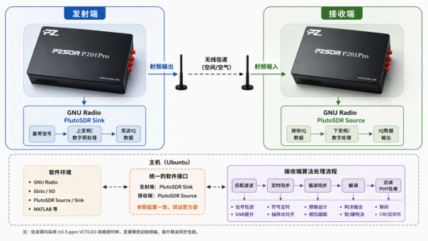
Experiment Setup & Receiver Parameters
Transmitter waveforms follow the general digital-modulation workflow introduced in earlier articles. Key experimental parameters are listed below:
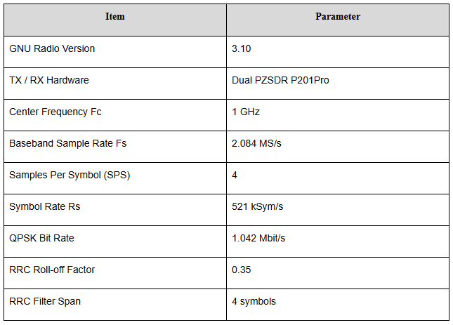
Rs = Fs / SPS = 2.084 MS/s / 4 = 521 kSym/s
Each QPSK symbol carries 2 bits: Rb = 2 × Rs = 1.042 Mbit/s
Figure 2. GNU Radio minimal receive chain flow-graph (Match Filter + visualization sinks)
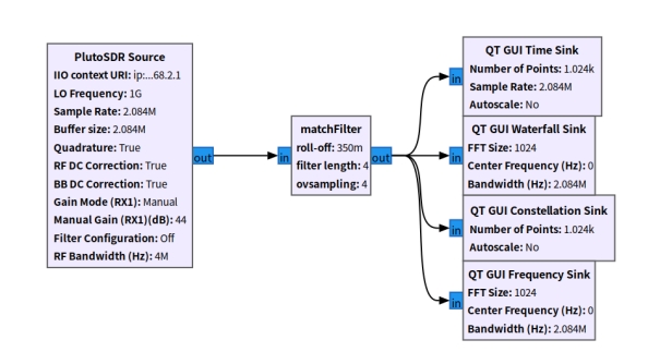
After launching the flow-graph, valid QPSK signals are visible on the spectrum plot and continuous IQ waveforms appear in the time-domain view. However, the constellation sink outputs chaotic scattered points instead of four distinct QPSK clusters.
Figure 3. SDR runtime capture — spectrum, time-domain IQ and disordered constellation after matched filtering
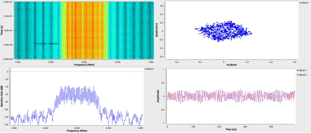
Key observation: Receiving RF signals does not equal successful symbol recovery.
1. What Do We Observe After Matched Filtering?
1.1 Role of the Matched Filter
The transmitter uses a Root-Raised-Cosine (RRC) filter for pulse shaping. The receiver implements an identical-parameter RRC matched filter.
Figure 4. Match Filter block parameters in GNU Radio
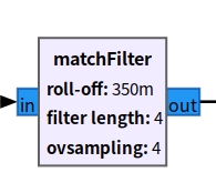
The matched filter maximizes SNR at the optimal symbol-sampling instant. Paired with the transmit shaping filter, it yields an overall near-ideal raised-cosine frequency response.
Note: The matched filter only performs filtering. It keeps 4 SPS output and does not identify which sample corresponds to the symbol center.
2. Why Perform Symbol Synchronization First?
2.1 Symbol Synchronization Answers: When to Sample?
This receiver uses the Gardner Symbol Sync block. Gardner timing error detection is non-decision-directed. It works even before carrier lock, while the constellation is still rotating.
Gardner Symbol Sync performs two critical tasks:
3. Adjust sampling phase to align output samples near symbol centers.
4. Convert input from 4 SPS down to 1 SPS.
2.2 From Chaotic Points to a Rotating Ring
After rejecting transitional oversample points, output samples align closely to true QPSK symbol amplitudes. Carrier frequency offset still exists, but amplitude structure becomes clear — producing the well-known intermediate state: rotating constellation ring.
Figure 5. Constellation evolution: chaotic scatter → rotating ring after Gardner timing sync
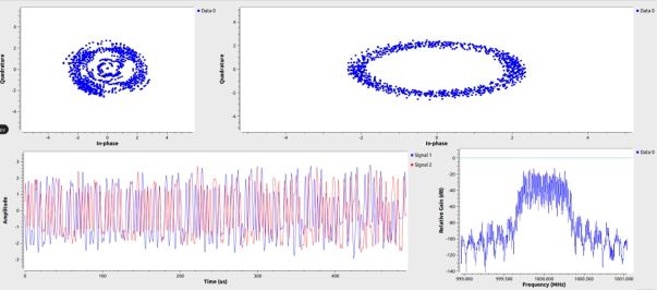
What this ring tells us:
· Optimal symbol sampling instants are mostly recovered.
· QPSK symbol-amplitude structure is stable.
· Symbol phase continuously drifts over time.
· Quadrant-based symbol decision cannot yet operate reliably.
Note: This processing order (timing sync before carrier sync) is for this specific test workflow. Architectures using Mueller–Müller timing or alternative carrier-acquisition blocks may reorder these stages.
3. Where Does the Rotating Ring Come From? — Understanding Residual CFO
Transmitter and receiver run from independent reference oscillators. Local-oscillator frequency mismatch creates residual Carrier Frequency Offset (CFO) after down-conversion.
Signal model after symbol synchronization: r[k] = s[k]·e^(j(2π·Δf·k/Rs + θ₀)) + w[k]
· s[k]: Transmitted QPSK symbol
· Δf: Carrier frequency offset
· θ₀: Initial static phase offset
· w[k]: Additive noise
Phase increment per symbol: Δφ = 2π·Δf/Rs
Phase error accumulates symbol-by-symbol. Over observation time, the four QPSK points rotate along the unit circle and stack into a ring on the constellation plot. Carrier synchronization (Costas Loop) must estimate this progressive rotation and apply inverse phase rotation to restore discrete symbol clusters.
4. How the Costas-Loop Stops Constellation Rotation
The Costas-Loop is a feedback loop that continuously measures phase error and applies corrective rotation to baseband samples.
Correction formula: y[k] = r[k]·e^(-j·θ̂[k])
Where θ̂[k] is the carrier-phase estimate generated by Costas-Loop.
Working principle:
5. Phase detector computes phase offset relative to ideal QPSK symbol quadrants.
6. Loop filter smooths error and updates frequency & phase estimates.
7. Numerically-Controlled Oscillator (NCO) generates inverse phase rotation to counteract CFO.
When loop tracking converges: θ̂[k] ≈ 2π·Δf·k/Rs + θ₀. Accumulating phase rotation is cancelled, and four QPSK clusters reappear on the constellation plot.
5. GNU Radio Practical Measurement: Rotating Ring to Four QPSK Clusters
Figure 6. Complete GNU Radio receive flow-graph: Matched Filter → Gardner Symbol Sync → Costas Loop + visualization sinks
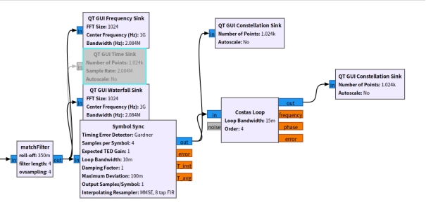
Pre-processing including gain tuning and timing synchronization is completed beforehand. We focus on constellation changes before and after Costas-Loop activation.
5.1 Before Costas-Loop: Rotating Ring
Timing synchronization is functional, but carrier phase remains uncompensated. Long-term constellation output forms a broad rotating ring.
5.2 Costas-Loop Configuration for QPSK
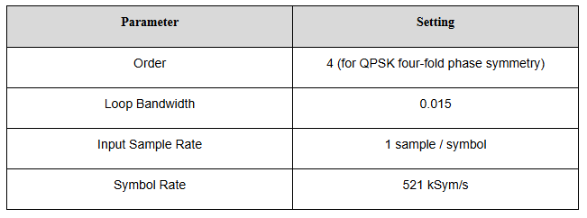
Note: Order=4 selects a QPSK-optimized phase detector. The underlying control loop remains a second-order loop.
5.3 Enabling Costas-Loop: Recover QPSK Clusters
Figure 7. Runtime screenshot: rotating ring converges into four distinct QPSK point clusters after Costas-Loop lock
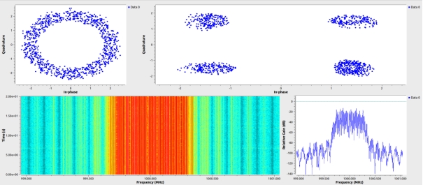
Observable transition: Rotating ring → gradual ring contraction → four-quadrant structure emerges → stable QPSK clusters.
Real-world hardware produces clusters with finite width caused by thermal noise, residual phase error, timing jitter and RF non-idealities, unlike mathematical simulation ideal points. The transformation from ring to four clusters verifies successful carrier synchronization.
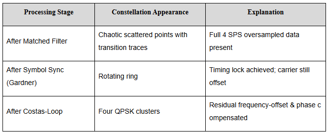
Figure 8. MATLAB idealized comparison of constellation three-stage evolution
6. What Does Loop Bandwidth Actually Control?
In GNU Radio Costas-Loop, Loop Bandwidth is the primary tuning parameter.
· Smaller bandwidth: Smoother estimation, better noise rejection; slower acquisition & tracking.
· Larger bandwidth: Faster CFO acquisition and phase tracking; more noise admitted into the loop.
· Moderate bandwidth balances acquisition speed versus steady-state cluster quality.
6.1 Mapping GRC Parameters to Second-Order-Loop Theory
GNU Radio 3.10 Costas-Loop builds on the generic control_loop second-order implementation. Only core parameters are exposed inside GRC. Internal damping factor defaults to ζ = √2/2 ≈ 0.7071.
Loop-gain calculation: D = 1 + 2ζω + ω², α = 4ζω/D, β = 4ω²/D
Loop state update per symbol: d_freq[k+1] = d_freq[k] + β·e[k]; d_phase[k+1] = d_phase[k] + d_freq[k+1] + α·e[k]
· α·e[k]: Fast phase correction term
· β·e[k]: Integrates error to build frequency-offset estimate over time
Three optional debug outputs are available:
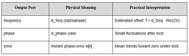
6.2 Loop Bandwidth Normalization Reference
Costas-Loop sits after Symbol Sync, so Loop Bandwidth is normalized against the 1 SPS symbol rate Rs = 521 ksample/s, not the original 2.084 MS/s sample rate.
Intuitive frequency-scale approximation: f_scale ≈ loop_bw · Rs/(2π)
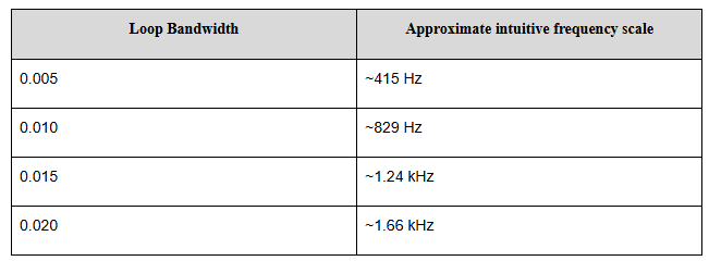
Note: This is an intuitive reference, not strict 3-dB loop noise bandwidth.
6.3 Simulation Comparison with Different Loop Bandwidth
Simulation conditions: QPSK, Rs = 521 kSym/s, residual CFO = 600 Hz, SNR = 16 dB, Loop Bandwidth swept: 0.005 / 0.010 / 0.015 / 0.020.
Figure 9. Simulation plots: frequency estimation convergence & residual phase error versus different loop bandwidth values
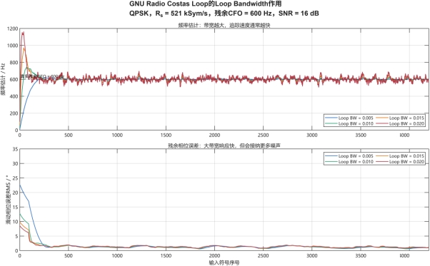
Figure 10. Trade-off chart: acquisition-speed vs steady-state phase noise for varying Loop Bandwidth
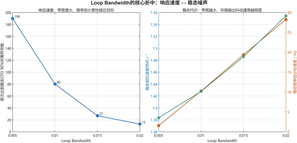
Key practical takeaway: Increasing Loop Bandwidth speeds ring-to-cluster convergence, yet excessive bandwidth widens final constellation clusters due to higher noise sensitivity. The value 0.015 used in this article is a balanced choice for this specific symbol-rate, CFO and SNR condition, not a universal fixed constant.
Important misconception: Loop Bandwidth does not directly define a hard maximum correctable CFO value. Capture performance depends additionally on phase-detector type, damping, initial phase, SNR and allowed lock time.
Summary
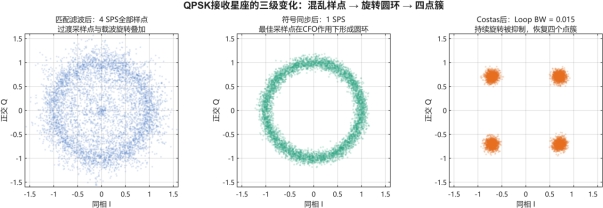
From raw PlutoSDR-Source IQ samples, the received constellation goes through three well-defined processing phases:
Figure 11. Infographic: three-stage constellation evolution: matched filter → Gardner symbol sync → Costas-Loop carrier sync
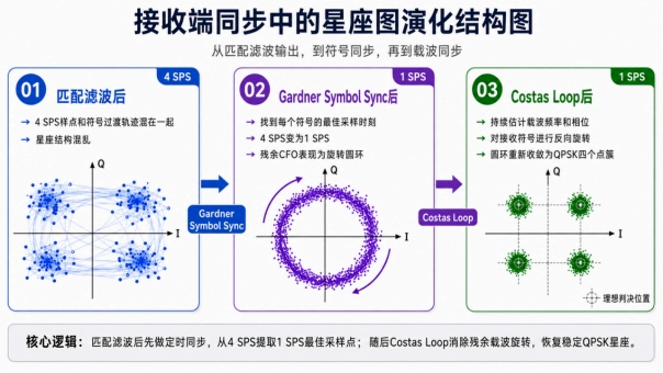
8. Matched-Filter output (4 SPS): Mixed oversampled points; highly disordered constellation.
9. Gardner Symbol-Sync output (1 SPS): Optimal symbol samples extracted; forms rotating ring due to residual CFO.
10. Costas-Loop output (1 SPS): Progressive phase rotation cancelled; four stable QPSK clusters recovered.
· Symbol synchronization answers: At what instant should I observe each symbol?
· Carrier synchronization answers: Why are my observed symbols still rotating?
· GNU Radio Loop Bandwidth sets the Costas-Loop compromise between fast tracking and steady-state noise performance.
In short: The Costas-Loop stops a spinning QPSK constellation and converts a rotating ring back into four decision-ready symbol clusters.
This is Part 2 of our GNU Radio digital-receiver series. Part 1 covered clock accuracy and carrier-frequency offset measurement.
Leave us a message
Puzhi focuses on SDR and ARM/FPGA technology solutions